
CORDIC算法详解(六)- CORDIC 算法的硬件实现
文章目录
网上有很多类似的介绍,但是本文会结合实例进行介绍,尽量以最简单的语言进行解析。
CORDIC ( Coordinate Rotation Digital Computer ) 是坐标旋转数字计算机算法的简称,
由 Vloder• 于 1959 年在设计美国航空导航控制系统的过程中首先提出[1], 主要用于解决导航系统中三角函数、 反三角函数和开方等运算的实时计算问题。 1971 年, Walther 将圆周系统、 线性系统和双曲系统统一到一个 CORDIC 迭代方程里 , 从而提出了一种统一的CORDIC 算法形式[2]。
CORDIC 算法应用广泛, 如离散傅里叶变换 、 离散余弦变换、 离散 Hartley 变换、Chirp-Z 变换、 各种滤波以及矩阵的奇异值分解中都可应用 CORDIC 算法。 从广义上讲,CORDIC 算法提供了一种数学计算的逼近方法。 由于它最终可分解为一系列的加减和移位操作, 故非常适合硬件实现。 例如, 在工程领域可采用 CORDIC 算法实现直接数字频率合成器。 本节在阐述 CORDIC 算法三种旋转模式的基础上, 介绍了利用 CORDIC 算法计算三角函数、 反三角函数和复数求模等相关理论。 以此为依据, 阐述了基于 FPGA 的 CORDIC 算法的设计与实现及其工程应用。
整个系列分别从圆周系统、 线性系统和双曲系统及硬件实现进行分析,如下:
6 CORDIC 算法的硬件实现
6.1 CORDIC 算法的硬件相关介绍
串行结构具体细节如图 3.95 所示。 图中 sgn(yi) 和 sgn(zi)分别表示yi和zi的符号位即最高位, 根据工作模式( 旋转模式还是向量模式) 的不同, 选择其中之一赋给di( 这里di为 1或者 0)。 加法器则根据di确定工作模式( 加法操作还是减法操作)。 “>> i ” 表示对输入数据右移i位, i 由 control 模块控制。 ROM 中存放的数据为每次迭代时的旋转角度tand-12-i ,可以用角度表示也可以用弧度表示, 统一即可。 串行结构的设计难点在于控制路径。 以 16次迭代为例, 即i= 0,1,2,…,15 , 设计一个模 16 的计数器 cnt 计数值由 0 至 15, 通过对计数值译码产生图中的 sel 信号, 即 cnt>0 时 sel 为 1, 否则为 0。 同时, 该计数值还可对移位量进行动态调整, 如图 3.96 所示。 此外, 该计数值还可以作为 ROM 的读地址。


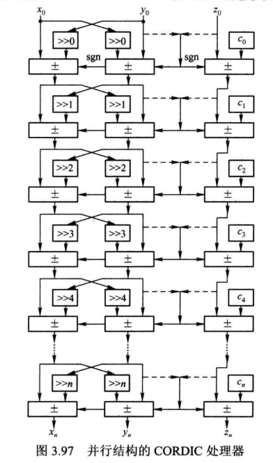
并行结构如 3.97 所示, 这里将旋转模式和向量模式的架构统一起来, 两者的区别只是在于图 3.97 中加法器的控制端。 旋转模式加法器的控制端来自于 zi 的符号位, 向量模式则来自于yi的符号位。 并行流水结构则是在并行结构的基础上对每级 CORDIC 处理单元的输出添加流水寄存器, 从而缩短关键路径, 提高系统处理速度。
6.2 CORDIC 算法的硬件实现(圆周系统)-Verilog版
6.2.1 源码
module Cordic_Test ( CLK_50M,RST_N, Phase, Sin,Cos,Error ); input CLK_50M; input RST_N; input [31:0] Phase; output [31:0] Sin; output [31:0] Cos; output [31:0] Error; `define rot0 32'd //45度*2^16 `define rot1 32'd //26.5651度*2^16 `define rot2 32'd //14.0362度*2^16 `define rot3 32'd //7.1250度*2^16 `define rot4 32'd //3.5763度*2^16 `define rot5 32'd //1.7899度*2^16 `define rot6 32'd58688 //0.8952度*2^16 `define rot7 32'd29312 //0.4476度*2^16 `define rot8 32'd14656 //0.2238度*2^16 `define rot9 32'd7360 //0.1119度*2^16 `define rot10 32'd3648 //0.0560度*2^16 `define rot11 32'd1856 //0.0280度*2^16 `define rot12 32'd896 //0.0140度*2^16 `define rot13 32'd448 //0.0070度*2^16 `define rot14 32'd256 //0.0035度*2^16 `define rot15 32'd128 //0.0018度*2^16 parameter Pipeline = 16; parameter K = 32'h09b74; //K=0.*2^16,32'h09b74, reg signed [31:0] Sin; reg signed [31:0] Cos; reg signed [31:0] Error; reg signed [31:0] x0=0,y0=0,z0=0; reg signed [31:0] x1=0,y1=0,z1=0; reg signed [31:0] x2=0,y2=0,z2=0; reg signed [31:0] x3=0,y3=0,z3=0; reg signed [31:0] x4=0,y4=0,z4=0; reg signed [31:0] x5=0,y5=0,z5=0; reg signed [31:0] x6=0,y6=0,z6=0; reg signed [31:0] x7=0,y7=0,z7=0; reg signed [31:0] x8=0,y8=0,z8=0; reg signed [31:0] x9=0,y9=0,z9=0; reg signed [31:0] x10=0,y10=0,z10=0; reg signed [31:0] x11=0,y11=0,z11=0; reg signed [31:0] x12=0,y12=0,z12=0; reg signed [31:0] x13=0,y13=0,z13=0; reg signed [31:0] x14=0,y14=0,z14=0; reg signed [31:0] x15=0,y15=0,z15=0; reg signed [31:0] x16=0,y16=0,z16=0; reg [ 1:0] Quadrant [Pipeline:0]; always @ (posedge CLK_50M or negedge RST_N) begin if(!RST_N) begin x0 <= 1'b0; y0 <= 1'b0; z0 <= 1'b0; end else begin x0 <= K; y0 <= 32'd0; z0 <= Phase[15:0] << 16; end end always @ (posedge CLK_50M or negedge RST_N) begin if(!RST_N) begin x1 <= 1'b0; y1 <= 1'b0; z1 <= 1'b0; end else if(z0[31]) begin x1 <= x0 + y0; y1 <= y0 - x0; z1 <= z0 + `rot0; end else begin x1 <= x0 - y0; y1 <= y0 + x0; z1 <= z0 - `rot0; end end always @ (posedge CLK_50M or negedge RST_N) begin if(!RST_N) begin x2 <= 1'b0; y2 <= 1'b0; z2 <= 1'b0; end else if(z1[31]) begin x2 <= x1 + (y1 >>> 1); y2 <= y1 - (x1 >>> 1); z2 <= z1 + `rot1; end else begin x2 <= x1 - (y1 >>> 1); y2 <= y1 + (x1 >>> 1); z2 <= z1 - `rot1; end end always @ (posedge CLK_50M or negedge RST_N) begin if(!RST_N) begin x3 <= 1'b0; y3 <= 1'b0; z3 <= 1'b0; end else if(z2[31]) begin x3 <= x2 + (y2 >>> 2); y3 <= y2 - (x2 >>> 2); z3 <= z2 + `rot2; end else begin x3 <= x2 - (y2 >>> 2); y3 <= y2 + (x2 >>> 2); z3 <= z2 - `rot2; end end always @ (posedge CLK_50M or negedge RST_N) begin if(!RST_N) begin x4 <= 1'b0; y4 <= 1'b0; z4 <= 1'b0; end else if(z3[31]) begin x4 <= x3 + (y3 >>> 3); y4 <= y3 - (x3 >>> 3); z4 <= z3 + `rot3; end else begin x4 <= x3 - (y3 >>> 3); y4 <= y3 + (x3 >>> 3); z4 <= z3 - `rot3; end end always @ (posedge CLK_50M or negedge RST_N) begin if(!RST_N) begin x5 <= 1'b0; y5 <= 1'b0; z5 <= 1'b0; end else if(z4[31]) begin x5 <= x4 + (y4 >>> 4); y5 <= y4 - (x4 >>> 4); z5 <= z4 + `rot4; end else begin x5 <= x4 - (y4 >>> 4); y5 <= y4 + (x4 >>> 4); z5 <= z4 - `rot4; end end always @ (posedge CLK_50M or negedge RST_N) begin if(!RST_N) begin x6 <= 1'b0; y6 <= 1'b0; z6 <= 1'b0; end else if(z5[31]) begin x6 <= x5 + (y5 >>> 5); y6 <= y5 - (x5 >>> 5); z6 <= z5 + `rot5; end else begin x6 <= x5 - (y5 >>> 5); y6 <= y5 + (x5 >>> 5); z6 <= z5 - `rot5; end end always @ (posedge CLK_50M or negedge RST_N) begin if(!RST_N) begin x7 <= 1'b0; y7 <= 1'b0; z7 <= 1'b0; end else if(z6[31]) begin x7 <= x6 + (y6 >>> 6); y7 <= y6 - (x6 >>> 6); z7 <= z6 + `rot6; end else begin x7 <= x6 - (y6 >>> 6); y7 <= y6 + (x6 >>> 6); z7 <= z6 - `rot6; end end always @ (posedge CLK_50M or negedge RST_N) begin if(!RST_N) begin x8 <= 1'b0; y8 <= 1'b0; z8 <= 1'b0; end else if(z7[31]) begin x8 <= x7 + (y7 >>> 7); y8 <= y7 - (x7 >>> 7); z8 <= z7 + `rot7; end else begin x8 <= x7 - (y7 >>> 7); y8 <= y7 + (x7 >>> 7); z8 <= z7 - `rot7; end end always @ (posedge CLK_50M or negedge RST_N) begin if(!RST_N) begin x9 <= 1'b0; y9 <= 1'b0; z9 <= 1'b0; end else if(z8[31]) begin x9 <= x8 + (y8 >>> 8); y9 <= y8 - (x8 >>> 8); z9 <= z8 + `rot8; end else begin x9 <= x8 - (y8 >>> 8); y9 <= y8 + (x8 >>> 8); z9 <= z8 - `rot8; end end always @ (posedge CLK_50M or negedge RST_N) begin if(!RST_N) begin x10 <= 1'b0; y10 <= 1'b0; z10 <= 1'b0; end else if(z9[31]) begin x10 <= x9 + (y9 >>> 9); y10 <= y9 - (x9 >>> 9); z10 <= z9 + `rot9; end else begin x10 <= x9 - (y9 >>> 9); y10 <= y9 + (x9 >>> 9); z10 <= z9 - `rot9; end end always @ (posedge CLK_50M or negedge RST_N) begin if(!RST_N) begin x11 <= 1'b0; y11 <= 1'b0; z11 <= 1'b0; end else if(z10[31]) begin x11 <= x10 + (y10 >>> 10); y11 <= y10 - (x10 >>> 10); z11 <= z10 + `rot10; end else begin x11 <= x10 - (y10 >>> 10); y11 <= y10 + (x10 >>> 10); z11 <= z10 - `rot10; end end always @ (posedge CLK_50M or negedge RST_N) begin if(!RST_N) begin x12 <= 1'b0; y12 <= 1'b0; z12 <= 1'b0; end else if(z11[31]) begin x12 <= x11 + (y11 >>> 11); y12 <= y11 - (x11 >>> 11); z12 <= z11 + `rot11; end else begin x12 <= x11 - (y11 >>> 11); y12 <= y11 + (x11 >>> 11); z12 <= z11 - `rot11; end end always @ (posedge CLK_50M or negedge RST_N) begin if(!RST_N) begin x13 <= 1'b0; y13 <= 1'b0; z13 <= 1'b0; end else if(z12[31]) begin x13 <= x12 + (y12 >>> 12); y13 <= y12 - (x12 >>> 12); z13 <= z12 + `rot12; end else begin x13 <= x12 - (y12 >>> 12); y13 <= y12 + (x12 >>> 12); z13 <= z12 - `rot12; end end always @ (posedge CLK_50M or negedge RST_N) begin if(!RST_N) begin x14 <= 1'b0; y14 <= 1'b0; z14 <= 1'b0; end else if(z13[31]) begin x14 <= x13 + (y13 >>> 13); y14 <= y13 - (x13 >>> 13); z14 <= z13 + `rot13; end else begin x14 <= x13 - (y13 >>> 13); y14 <= y13 + (x13 >>> 13); z14 <= z13 - `rot13; end end always @ (posedge CLK_50M or negedge RST_N) begin if(!RST_N) begin x15 <= 1'b0; y15 <= 1'b0; z15 <= 1'b0; end else if(z14[31]) begin x15 <= x14 + (y14 >>> 14); y15 <= y14 - (x14 >>> 14); z15 <= z14 + `rot14; end else begin x15 <= x14 - (y14 >>> 14); y15 <= y14 + (x14 >>> 14); z15 <= z14 - `rot14; end end always @ (posedge CLK_50M or negedge RST_N) begin if(!RST_N) begin x16 <= 1'b0; y16 <= 1'b0; z16 <= 1'b0; end else if(z15[31]) begin x16 <= x15 + (y15 >>> 15); y16 <= y15 - (x15 >>> 15); z16 <= z15 + `rot15; end else begin x16 <= x15 - (y15 >>> 15); y16 <= y15 + (x15 >>> 15); z16 <= z15 - `rot15; end end always @ (posedge CLK_50M or negedge RST_N) begin if(!RST_N) begin Quadrant[0] <= 1'b0; Quadrant[1] <= 1'b0; Quadrant[2] <= 1'b0; Quadrant[3] <= 1'b0; Quadrant[4] <= 1'b0; Quadrant[5] <= 1'b0; Quadrant[6] <= 1'b0; Quadrant[7] <= 1'b0; Quadrant[8] <= 1'b0; Quadrant[9] <= 1'b0; Quadrant[10] <= 1'b0; Quadrant[11] <= 1'b0; Quadrant[12] <= 1'b0; Quadrant[13] <= 1'b0; Quadrant[14] <= 1'b0; Quadrant[15] <= 1'b0; Quadrant[16] <= 1'b0; end else begin Quadrant[0] <= Phase[17:16]; Quadrant[1] <= Quadrant[0]; Quadrant[2] <= Quadrant[1]; Quadrant[3] <= Quadrant[2]; Quadrant[4] <= Quadrant[3]; Quadrant[5] <= Quadrant[4]; Quadrant[6] <= Quadrant[5]; Quadrant[7] <= Quadrant[6]; Quadrant[8] <= Quadrant[7]; Quadrant[9] <= Quadrant[8]; Quadrant[10] <= Quadrant[9]; Quadrant[11] <= Quadrant[10]; Quadrant[12] <= Quadrant[11]; Quadrant[13] <= Quadrant[12]; Quadrant[14] <= Quadrant[13]; Quadrant[15] <= Quadrant[14]; Quadrant[16] <= Quadrant[15]; end end always @ (posedge CLK_50M or negedge RST_N) begin if(!RST_N) begin Cos <= 1'b0; Sin <= 1'b0; Error <= 1'b0; end else begin Error <= z16; case(Quadrant[16]) 2'b00: //if the Phase is in first Quadrant,the Sin(X)=Sin(A),Cos(X)=Cos(A) begin Cos <= x16; Sin <= y16; end 2'b01: //if the Phase is in second Quadrant,the Sin(X)=Sin(A+90)=CosA,Cos(X)=Cos(A+90)=-SinA begin Cos <= ~(y16) + 1'b1;//-Sin Sin <= x16;//Cos end 2'b10: //if the Phase is in third Quadrant,the Sin(X)=Sin(A+180)=-SinA,Cos(X)=Cos(A+180)=-CosA begin Cos <= ~(x16) + 1'b1;//-Cos Sin <= ~(y16) + 1'b1;//-Sin end 2'b11: //if the Phase is in forth Quadrant,the Sin(X)=Sin(A+270)=-CosA,Cos(X)=Cos(A+270)=SinA begin Cos <= y16;//Sin Sin <= ~(x16) + 1'b1;//-Cos end endcase end end endmodule 6.2.2 仿真代码TB
`timescale 1 ps/ 1 ps module Cordic_Test_tb; // Inputs reg CLK_50M; reg RST_N; reg [15:0] cnt; reg [15:0] cnt_n; reg [31:0] Phase; reg [31:0] Phase_n; wire [31:0] Sin; wire [31:0] Cos; wire [31:0] Error; // Instantiate the Unit Under Test (UUT) Cordic_Test uut ( .CLK_50M (CLK_50M ), .RST_N (RST_N ), .Phase (Phase ), .Sin (Sin ), .Cos (Cos ), .Error (Error ) ); initial begin #0 CLK_50M = 1'b0; #10000 RST_N = 1'b0; #10000 RST_N = 1'b1; # $stop; end always #10000 begin CLK_50M = ~CLK_50M; end always @ (posedge CLK_50M or negedge RST_N) begin if(!RST_N) cnt <= 1'b0; else cnt <= cnt_n; end always @ (*) begin if(cnt == 16'd359) cnt_n = 1'b0; else cnt_n = cnt + 1'b1; end //生成相位0-359度,Phase[17:16]为相位的象限,Phase[15:10]为相位的值 always @ (posedge CLK_50M or negedge RST_N) begin if(!RST_N) Phase <= 1'b0; else Phase <= Phase_n; end always @ (*) begin if(cnt <= 16'd90) Phase_n = cnt; else if(cnt > 16'd90 && cnt <= 16'd180) Phase_n = {2'b01,cnt - 16'd90}; else if(cnt > 16'd180 && cnt <= 16'd270) Phase_n = {2'b10,cnt - 16'd180}; else if(cnt > 16'd270) Phase_n = {2'b11,cnt - 16'd270}; end endmodule 6.2.3 流程总结
简单总结下流程,Cordic算法旋转模式使用Verilog HDL的实现流程
- (1) 确定迭代次数,将每次迭代的角度计算出来,预先定义为参数,为了避免浮点运算,将角度值向左移位16位,取整数部分。
- (2)
根据迭代公式进行迭代计算,本设计取16次迭代,当迭代次数越大时,1/∏cosθi会趋向于一个确定值。如果对结果精度要求更高,可以设置更高的迭代次数,根据迭代次数,可以将伸缩因子KN = 1/∏cosθi计算出来。同样将其左移16位。 - (3) 设置x0 = ∏cosθi,y0 = 0,则求出x16 = cosθ,y16 = sinθ。
例如1010_1010, []是添加的位
逻辑左移一位:0101_010[0]
算数左移一位:0101_010[0]
逻辑右移一位:[0]101_0101
算数右移一位:[1]101_0101
如果角度在第一象限,sin(x) = sin(a),cos(x) = sin(a)最后的结果x16 = cosθ, y16 = sinθ,这里我想起了那句口诀,一全正,二正弦,三正切,四余弦
如果角度在第二象限,sin(x) = sin(a+90) = cos(a),cos(x) = cos(a+90) = -sin(a)
如果角度在第三象限,sin(x) = sin(a+180) = -sin(a),cos(x) = cos(a+180) = -cos(a)
如果角度在第四象限,sin(x) = sin(a+270) = cos(a),cos(x) = cos(a+270) = -sin(a)
对于正数,我们直接赋值输出,负数,这里使用有符号数表示,将其取反加1即可。
6.2.4 仿真过程注意事项
6.2.4.1 显示模拟波形(即sin/cos波形)需要怎么设置modelsim
- 1、选择sin/cos信号,右击—->Radix—->Symbolic
- 2、选择sin/cos信号,右击—->Format—->Analog(automatic)
6.2.4.2 仿真时间

- 选择sin/cos信号,右击—->Format—->Analog(custom) 还可以对显示波形进行相关设置,可以自己去尝试

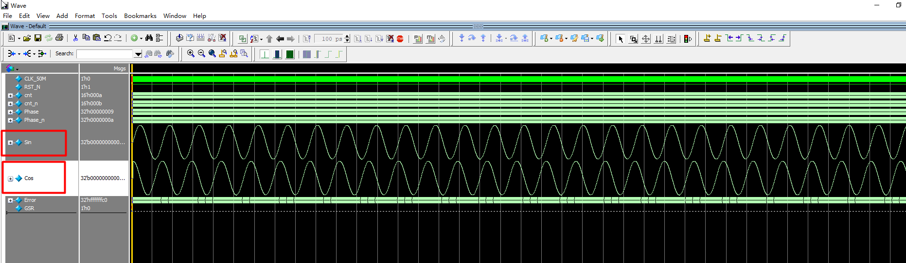
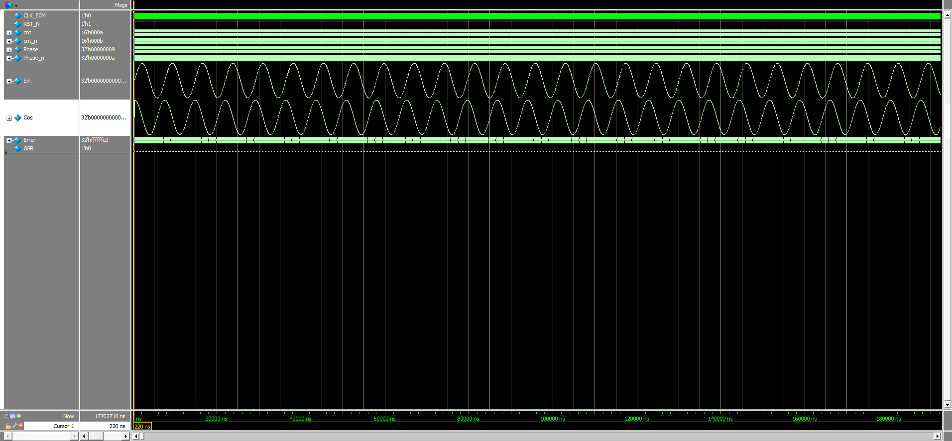
6.2.5 仿真结果
6.2.6 工程源码
6.3 CORDIC 算法的硬件实现(圆周系统)- 基于System Generator
发布者:全栈程序员-站长,转载请注明出处:https://javaforall.net/214547.html原文链接:https://javaforall.net