
1、实验环境
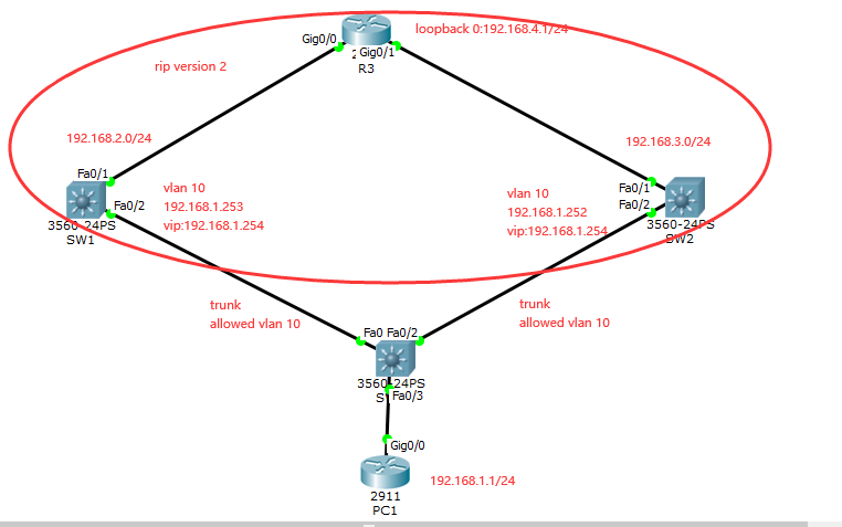
使用cisco packet tracer模拟器实现网络拓扑配置,交换机使用3560,路由器使用2911。
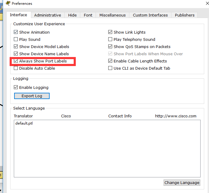
显示所有端口
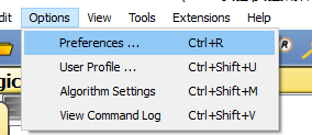

Options–>Preferences–>选中Always Show Port Labels:
2、网络拓扑如下
3、具体配置
PC1目前只需要配置基础ip即可:
我们使用路由器来模拟PC机
Router>en
Router#conf t
Router(config)#interface GigabitEthernet0/0
Router(config-if)#ip address 192.168.1.1 255.255.255.0
Router(config-if)#no shutdown
Router(config-if)#end
Router#write
配置SW1,SW2,SW3基础ip,其中SW1和SW2做三层交换机使用,SW3做为二层交换机使用。
SW3:
Switch>en
Switch#conf t
Switch(config)#vlan 10
Switch(config-vlan)#exit
Switch(config)#interface FastEthernet0/3
Switch(config-if)#switchport mode access
Switch(config-if)#switchport access vlan 10
Switch(config-if)#exit
Switch(config)#interface FastEthernet0/1
Switch(config-if)#switchport trunk encapsulation dot1q
Switch(config-if)#switchport mode trunk
Switch(config-if)#switchport trunk allowed vlan 10
Switch(config-if)#exit
Switch(config)#interface FastEthernet0/2
Switch(config-if)#switchport trunk encapsulation dot1q
Switch(config-if)#switchport mode trunk
Switch(config-if)#switchport trunk allowed vlan 10
Switch(config-if)#end
Switch#write
SW1:
Switch>en
Switch#conf t
Switch(config)#vlan 10
Switch(config-vlan)#exit
Switch(config)#interface FastEthernet0/2
Switch(config-if)#switchport trunk encapsulation dot1q
Switch(config-if)#switchport mode trunk
Switch(config-if)#switchport trunk allowed vlan 10
Switch(config-if)#exit
Switch(config)#interface FastEthernet0/1
Switch(config-if)#no switchport
Switch(config-if)#ip address 192.168.2.1 255.255.255.0
Switch(config-if)#exit
Switch(config)#interface vlan 10
Switch(config-if)#ip address 192.168.1.252 255.255.255.0
Switch(config-if)#exit
SW2:
Switch>en
Switch#conf t
Switch(config)#vlan 10
Switch(config-vlan)#exit
Switch(config)#interface FastEthernet0/2
Switch(config-if)#switchport trunk encapsulation dot1q
Switch(config-if)#switchport mode trunk
Switch(config-if)#switchport trunk allowed vlan 10
Switch(config-if)#exit
Switch(config)#interface FastEthernet0/1
Switch(config-if)#no switchport
Switch(config-if)#ip address 192.168.3.1 255.255.255.0
Switch(config-if)#exit
Switch(config)#interface vlan 10
Switch(config-if)#ip address 192.168.1.253 255.255.255.0
Switch(config-if)#exit
此时从PC1上去ping SW1和SW2的vlan接口ip是能通的:
Router#ping 192.168.1.253
Type escape sequence to abort.
Sending 5, 100-byte ICMP Echos to 192.168.1.253, timeout is 2 seconds:
!!!!!
Success rate is 100 percent (5/5), round-trip min/avg/max = 0/0/1 ms
Router#ping 192.168.1.252
Type escape sequence to abort.
Sending 5, 100-byte ICMP Echos to 192.168.1.252, timeout is 2 seconds:
!!!!!
Success rate is 100 percent (5/5), round-trip min/avg/max = 0/0/1 ms
Router#
配置SW1和SW2上的hsrp,我们通过优先级控制SW1为主设备,SW2为备用设备
SW1:
en
conf t
Switch(config)#interface vlan 10
Switch(config-if)#standby 1 ip 192.168.1.254
Switch(config-if)#standby 1 priority 200
Switch(config-if)#standby 1 preempt
SW2:
en
conf t
Switch(config)#interface vlan 10
Switch(config-if)#standby 1 ip 192.168.1.254
Switch(config-if)#standby 1 priority 195
Switch(config-if)#standby 1 preempt
此时查看hsrp协议状态:
SW1:
Switch#show standby brief
P indicates configured to preempt.
|
Interface Grp Pri P State Active Standby Virtual IP
Vl10 1 200 P Active local 192.168.1.252 192.168.1.254
Switch#
SW2:
Switch#show standby brief
P indicates configured to preempt.
|
Interface Grp Pri P State Active Standby Virtual IP
Vl10 1 195 P Standby 192.168.1.253 local 192.168.1.254
Switch#
可以看到由于SW1优先级为200,高于SW2的195的优先级,所以SW1是active的,作为主设备;SW2是standby的。
配置出口路由器R3
Router>en
Router#conf t
Router(config)#interface GigabitEthernet0/0
Router(config-if)#no shutdown
Router(config-if)#ip address 192.168.2.2 255.255.255.0
Router(config-if)#exit
Router(config)#interface GigabitEthernet0/1
Router(config-if)#no shutdown
Router(config-if)#ip address 192.168.3.2 255.255.255.0
Router(config-if)#exit
Router(config)#interface loopback 0
Router(config-if)#no shutdown
Router(config-if)#ip address 192.168.4.1 255.255.255.0
Router(config-if)#exit
配置SW1、SW2和R3上三层设备的rip协议,当然也可以使用静态路由,我们这里使用rip。
SW1:
Switch#conf t
Switch(config)#ip routing
Switch(config)#router rip
Switch(config-router)#version 2
Switch(config-router)#no auto-summary
Switch(config-router)#network 192.168.1.0
Switch(config-router)#network 192.168.2.0
Switch(config-router)#end
SW2:
Switch#conf t
Switch(config)#ip routing
Switch(config)#router rip
Switch(config-router)#version 2
Switch(config-router)#no auto-summary
Switch(config-router)#network 192.168.1.0
Switch(config-router)#network 192.168.3.0
Switch(config-router)#end
R3:
Router#conf t
Router(config)#ip routing
Router(config)#router rip
Router(config-router)#version 2
Router(config-router)#no auto-summary
Router(config-router)#network 192.168.2.0
Router(config-router)#network 192.168.3.0
Router(config-router)#network 192.168.4.0
分别查看三台设备的路由:
SW1:
Switch#show ip route
Codes: C – connected, S – static, I – IGRP, R – RIP, M – mobile, B – BGP
D – EIGRP, EX – EIGRP external, O – OSPF, IA – OSPF inter area
N1 – OSPF NSSA external type 1, N2 – OSPF NSSA external type 2
E1 – OSPF external type 1, E2 – OSPF external type 2, E – EGP
i – IS-IS, L1 – IS-IS level-1, L2 – IS-IS level-2, ia – IS-IS inter area
* – candidate default, U – per-user static route, o – ODR
P – periodic downloaded static route
Gateway of last resort is not set
C 192.168.1.0/24 is directly connected, Vlan10
C 192.168.2.0/24 is directly connected, FastEthernet0/1
R 192.168.3.0/24 [120/1] via 192.168.2.2, 00:00:14, FastEthernet0/1
[120/1] via 192.168.1.252, 00:00:14, Vlan10
R 192.168.4.0/24 [120/1] via 192.168.2.2, 00:00:14, FastEthernet0/1
Switch#
可以看到192.168.1.0和192.168.2.0是直连路由,192.168.3.0和192.168.4.0是通过rip协议获取到的路由。
SW2:
Switch#show ip route
Codes: C – connected, S – static, I – IGRP, R – RIP, M – mobile, B – BGP
D – EIGRP, EX – EIGRP external, O – OSPF, IA – OSPF inter area
N1 – OSPF NSSA external type 1, N2 – OSPF NSSA external type 2
E1 – OSPF external type 1, E2 – OSPF external type 2, E – EGP
i – IS-IS, L1 – IS-IS level-1, L2 – IS-IS level-2, ia – IS-IS inter area
* – candidate default, U – per-user static route, o – ODR
P – periodic downloaded static route
Gateway of last resort is not set
C 192.168.1.0/24 is directly connected, Vlan10
R 192.168.2.0/24 [120/1] via 192.168.3.2, 00:00:06, FastEthernet0/1
[120/1] via 192.168.1.253, 00:00:02, Vlan10
C 192.168.3.0/24 is directly connected, FastEthernet0/1
R 192.168.4.0/24 [120/1] via 192.168.3.2, 00:00:06, FastEthernet0/1
Switch#
SW2上192.168.1.0和192.168.3.0是直连路由,而192.168.2.0和192.168.4.0是rip协议获取到的。
Router#show ip route
Codes: L – local, C – connected, S – static, R – RIP, M – mobile, B – BGP
D – EIGRP, EX – EIGRP external, O – OSPF, IA – OSPF inter area
N1 – OSPF NSSA external type 1, N2 – OSPF NSSA external type 2
E1 – OSPF external type 1, E2 – OSPF external type 2, E – EGP
i – IS-IS, L1 – IS-IS level-1, L2 – IS-IS level-2, ia – IS-IS inter area
* – candidate default, U – per-user static route, o – ODR
P – periodic downloaded static route
Gateway of last resort is not set
R 192.168.1.0/24 [120/1] via 192.168.3.1, 00:00:22, GigabitEthernet0/1
192.168.2.0/24 is variably subnetted, 2 subnets, 2 masks
C 192.168.2.0/24 is directly connected, GigabitEthernet0/0
L 192.168.2.2/32 is directly connected, GigabitEthernet0/0
192.168.3.0/24 is variably subnetted, 2 subnets, 2 masks
C 192.168.3.0/24 is directly connected, GigabitEthernet0/1
L 192.168.3.2/32 is directly connected, GigabitEthernet0/1
192.168.4.0/24 is variably subnetted, 2 subnets, 2 masks
C 192.168.4.0/24 is directly connected, Loopback0
L 192.168.4.1/32 is directly connected, Loopback0
Router#
R3上192.168.2.0、192.168.3.0和192.168.4.0都是直连路由,而192.168.1.0是通过rip协议获取到的。
此时我们试试从PC1上ping R3上的loopback0上的192.168.4.1看看:
Router#ping 192.168.4.1
Type escape sequence to abort.
Sending 5, 100-byte ICMP Echos to 192.168.4.1, timeout is 2 seconds:
…..
Success rate is 0 percent (0/5)
发现不通,而此时PC1到SW1和SW2的都是通的,这是由于PC1到SW1和SW2是直接通过二层vlan透传的,但是在到R3的时候,由于是三层通信了,所以必须得有路由。而我们使用的是路由器模拟PC机,无法直接在接口上配置网关,所以可以通过在PC1上增加一条默认路由器出去即可。
PC1:
Router#conf t
Router(config)#ip route 0.0.0.0 0.0.0.0 192.168.1.254
此时在ping192.168.4.1即可发现通了:
Router#ping 192.168.4.1
Type escape sequence to abort.
Sending 5, 100-byte ICMP Echos to 192.168.4.1, timeout is 2 seconds:
!!!!!
Success rate is 100 percent (5/5), round-trip min/avg/max = 0/3/12 ms
Router#write
此时我们测试在主设备SW1的上行端口down掉了以后,通过配置track主设备的上行端口进行主备切换
Switch>en
Switch#conf t
Switch(config)#interface vlan 10
Switch(config-if)#standby 1 track FastEthernet0/1
Switch(config-if)#exit
手工shutdown模拟端口故障:
Switch(config)#interface FastEthernet0/1
Switch(config-if)#shutdown
Switch(config-if)#end
Switch#show standby brief
P indicates configured to preempt.
|
Interface Grp Pri P State Active Standby Virtual IP
Vl10 1 190 P Standby 192.168.1.252 local 192.168.1.254
Switch#
此时我们看到SW1已经变成standby了。
SW2:
Switch>en
Switch#show standby brief
P indicates configured to preempt.
|
Interface Grp Pri P State Active Standby Virtual IP
Vl10 1 195 P Active local 192.168.1.253 192.168.1.254
Switch#
此时我们看到SW2变成了active状态了。在主设备上没有配置上行端口down了以后优先级减多少的情况下,默认优先级是减10的。
此时我们在PC1上ping R3上的192.168.4.1,还是能ping通的
Router#ping 192.168.4.1
Type escape sequence to abort.
Sending 5, 100-byte ICMP Echos to 192.168.4.1, timeout is 2 seconds:
!!!!!
Success rate is 100 percent (5/5), round-trip min/avg/max = 0/2/11 ms
Router#
此时我们去SW1上把上行接口起起来:
SW1:
Switch#conf t
Switch(config)#interface FastEthernet0/1
Switch(config)#interface FastEthernet0/1
%LINEPROTO-5-UPDOWN: Line protocol on Interface FastEthernet0/1, changed state to up
起起来立马就能在打印的日志里面看到状态有standby变成了active了。
我们来分别检查一下SW1和SW2:
SW1:
Switch#show standby brief
P indicates configured to preempt.
|
Interface Grp Pri P State Active Standby Virtual IP
Vl10 1 200 P Active local 192.168.1.252 192.168.1.254
Switch#
SW2:
Switch#show standby brief
P indicates configured to preempt.
|
Interface Grp Pri P State Active Standby Virtual IP
Vl10 1 195 P Standby 192.168.1.253 local 192.168.1.254
Switch#
发现SW1已经变成了主设备active的状态。因为我们主备上面都配置了抢占,所以主设备在恢复的时候能立马抢占回主设备的角色。
此时我们在测试一下连通性
在PC1上ping R3的loopback0
Router#ping 192.168.4.1
Type escape sequence to abort.
Sending 5, 100-byte ICMP Echos to 192.168.4.1, timeout is 2 seconds:
!!!!!
Success rate is 100 percent (5/5), round-trip min/avg/max = 0/0/1 ms
Router#
仍然是通的,实验到此结束。
发布者:全栈程序员-站长,转载请注明出处:https://javaforall.net/233070.html原文链接:https://javaforall.net